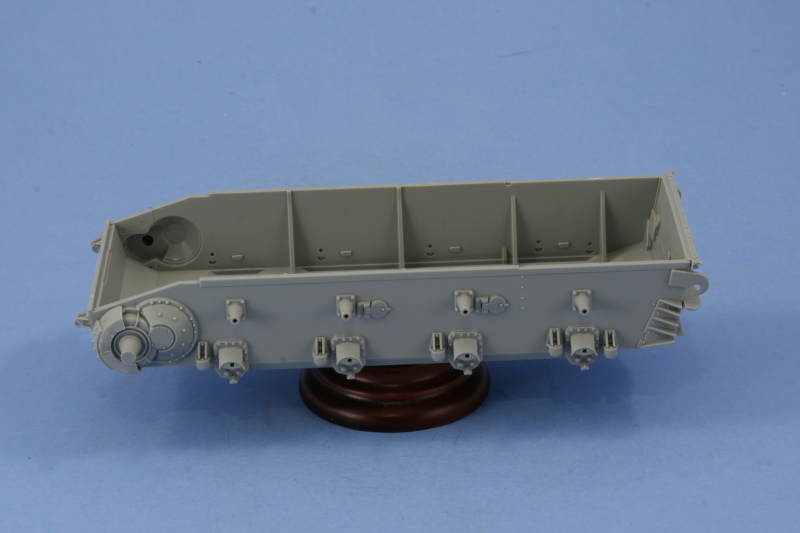
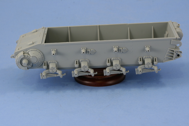
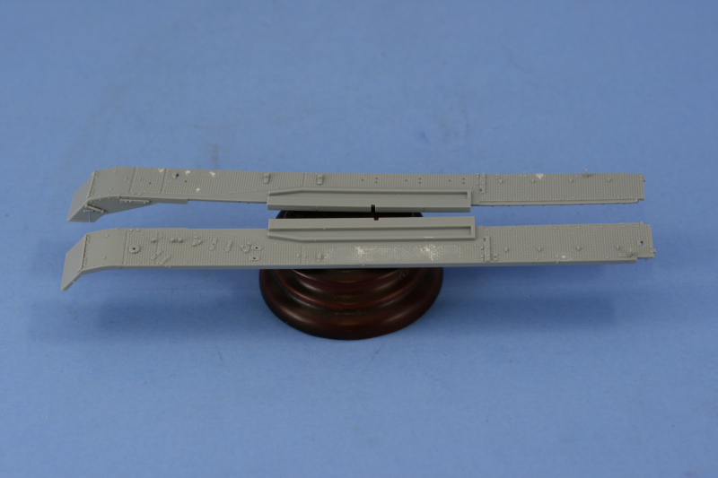
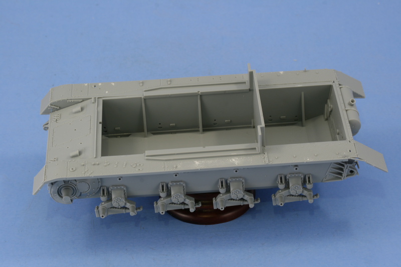
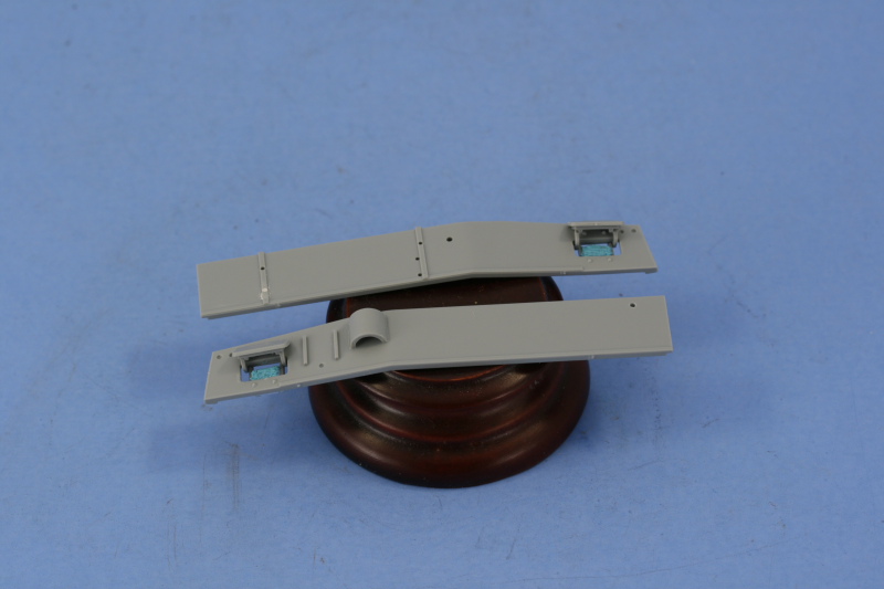
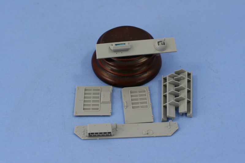
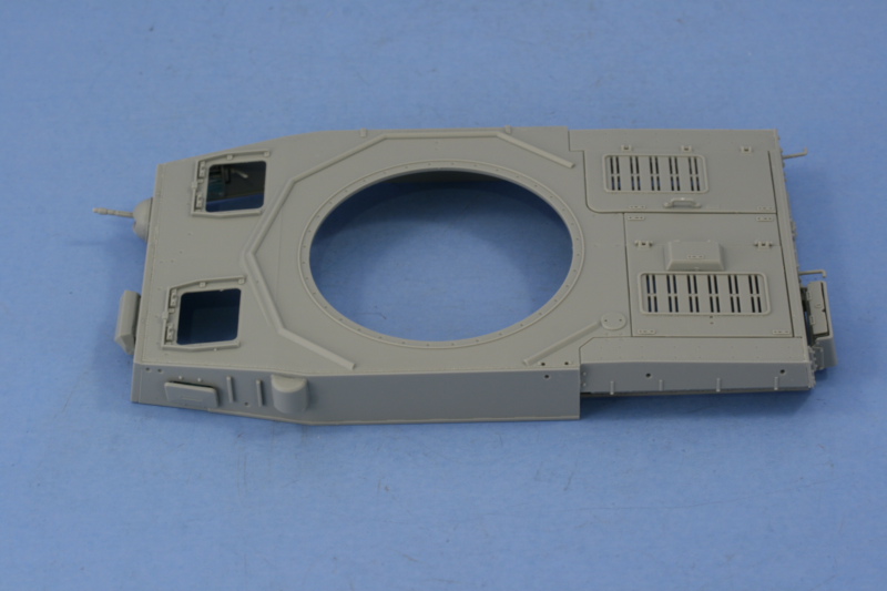
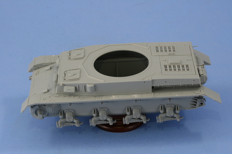
Lots of work was completed today so I'll dive right in...beginning first with the right side fender and Step 13, it received similar treatment as the left side yesterday. The intake flaps were installed along with the antenna tray and antenna, the PE fender support bracket, etc. All of the tools were left off with the exception of the track changing tool, this needed to be installed because of the overlap with the front fender support bracket...experience with the G taught me this one can't be fitted later on if the bracket is already in place, so on it goes. The Griffon clamps for the short pry-bar, the shovel, the crank starter, and the axe were also installed.

All of the tools that were left off had their molded on clamps carefully removed and their handles sanded down where appropriate. I assembled the multi-part jack but left the brackets off for now for easier painting. Because of where the jack installs, I'm going to save it for later as I have plans for some extra track links on that side of the hull and need access to it.

The three individual links that install on this fender also got some attention. They are molded solid but without the linking pins, so I used a pin vise and micro drill bit to open the holes up. There were also two small ejector pin marks on the top portion of their clamps that had to be carefully removed.

To round things out with the lower hull, I scratch-built two spare wheel holders from 24-gauge steel wire. I used blue tack to hold a wheel together as a template as a temporary solution, bent the wire to shape, then adjusted until I had the spacing right...it took 3 attempts before I got it down, but was worth it. Once I had one the right shape, making the second one was a piece of cake. The wire was mounted using CA gel so it could support the weight. I had considered using solder but didn't think it would keep its shape over time so went with the sturdier steel wire just to be sure.


Step 14 begins work on the turret by focusing first on the main gun. The mantle is constructed from 5 parts and the option is given to fit the sleeve 2 different ways, changing the placement of the screws in the process. I didn't really pick one over the other as the photos I'm using aren't clear enough to say one way or the other. This step also provides the option of installing the coaxial MG sleeve with the barrel present or not...a handy thing if you wanted to show the coaxial MG missing (ad hoc AA mount, wreck that's been picked over, etc.), I of course chose it with the MG in place.

Step 15 assembles the rest of the main gun by adding the barrel, the recoil housing, the mount into the turret, and the muzzle brake. This step also calls for the installation of the mount swivel points, parts B11 and B12, but I left them off because if you install them later, the gun will be movable if you're careful with the glue and don't attach them to the pins on B34...something Step 15 doesn't point out. The muzzle brake is two parts but use of liquid glue and careful sanding will create a seamless look. The slight seam on the one-piece barrel was also carefully sanded down to complete things here.

Step 16 installs the gun into the front turret plate and adds the breech and recoil guards. There are two sub-steps, one calls for the front turret plate to have the two view ports added, I elected to pose the gunner's in the open position. The other calls for the assembly of the breech and breech block.

The gun was installed into the turret front plate first and then the breech and recoil guards added to complete the step.

Step 17 is a collection of sub-steps dealing with the turret and turret accessories. The first is a busy one dealing with the turret interior. Both the side vision ports are installed and can be made workable if careful with the glue. I plan to leave the gunner's side open when the build is finished but for now it's in the closed position. The inner frames for the turret side hatches, parts G18, should also install in this step and they are shown in place on the diagram but they aren't called out by parts number or arrows, so this is a potential pitfall. If the frames aren't installed, it makes it much more difficult to get the side hatch hinges and outer doors in the correct position.
This little sub-step also adds the rear turret pistol ports and the lifting eyes. It directs you to install the exhaust fan but I left this off until the next step as it needs to integrate with some of the top parts and that's difficult to do at this point since they aren't installed yet.

The other sub-steps deal with the rear turret stowage box and the commander's cupola. The cupola is a multi-part assembly with options to pose the armored shutters in the open or closed position. Since these were operated independently, I elected to open only the front facing port and left all the others in the closed position. The hatches were installed in the closed position and are a very tight fit with the hinge points so be careful here or you can damage the pins.

Step 18 is the moment of truth...it assembles all the previous sub-assemblies to construct the turret and add its remaining details. To construct the turret you must first add the main gun and front plate to the top, then add the turret bottom. If you add the bottom first, the gun breech won't fit in the gap available, so the order of things is important here. I used a combination of regular glue, liquid glue, and strategic finger pressure to get all the weld seams to join and seal up properly.
Once dry, the details were added. I removed the molded on base of the commander's sighting vane and used the kit-provided PE replacement and installed the ventilator cover and signal port flap. The side hatches were assembled and installed and while the diagram is a bit confusing and has a couple of the hinge parts swapped around in the numbering, so long as the inner bases were installed in the previous step you can't install things wrong. The inner bases have two different sized "D" shaped pins that correspond to the correct hinge parts and so long as you have the pistol port door as the rearmost door on either side, everything goes in just fine. The instructions have an error in the parts number for the rain gutters, these are not A39 as labelled but are actually A37.
Last but not least, the cupola and storage box were installed.

And, just to stay in the spirit of things, Step 19 calls for the turret to be fitted to the lower hull.

Things are now ready to move to the painting stage.
Total session time: 8.25 hours
Total time to date: 25.25 hours
