Another weekend means another project! This particular project is one that has been waiting quietly for some time in the background and its turn finally came. I will be building Tamiya's Marder III kit #35248 with a variety of aftermarket goodies including Tristar's Pz 38t Interior once it arrives...and the fact that it hasn't arrived yet is going to make the build order for this one a little unorthodox!
Since I'm intending to use elements from both the Verlinden and the Tristar interior set, I can't start on that until I have both on hand and can see how they will interact with each other. This means that I can't build up the lower hull tub yet or do anything with the lower hull or suspension for that matter. The only area I can safely work on at the moment is the gun, so I skipped ahead to Step 18 in the instructions and started work there.
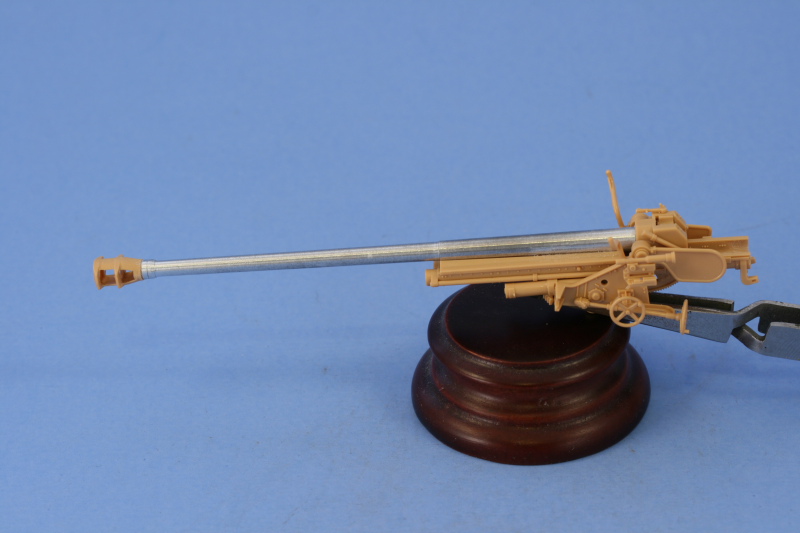
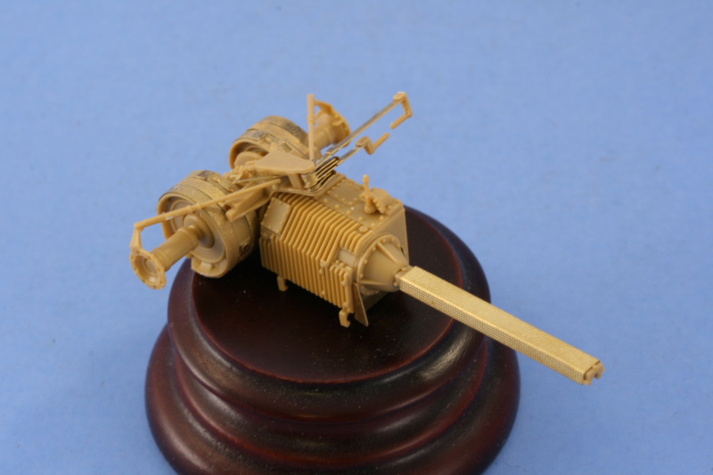
My first order of business was to work with the gun itself. Step 18 directs the assembly of the two-part gun barrel and its attachment to the breech block and recoil tray. Since I was replacing the barrel with the JR aluminum barrel, this step was heavily modified. The breech part already had an opening to take the base of the Tamiya barrel but its diameter was too large vs. the mount pin on the base of the JR barrel. To resolve this, I used some Aves Apoxysculpt two-part putty and packed that into the base. Some CA gel was then used to secure it firmly in place and CA gel used to glue the barrel to the recoil sled.
Another challenge immediately presented itself in the form of the JR white metal muzzle brake being totally inaccurate. Compared to scale drawings in Nuts & Bolts #15 and the kit parts, it proved to be undersized in every way and looks more like a Pak 40 brake than the brake used on the re-chambered Russian 7.62cm Pak 36(r). To resolve this, I went ahead and glued the two halves of the kit supplied barrel together at the front and let it dry, then used a razor saw to remove the brake portion. The brake was carefully trimmed and sanded until it matched to the barrel. Because I needed some working time with the alignment, I used Gator Grip glue instead of CA and set it off to the side to dry overnight.

The other half of Step 18 calls for the assembly of the gun mount and tray. The tray is a two-part assembly and it required some attention in terms of removing some ejector marks that would be visible inside the tray and dealing with the seam down the middle. I used liquid glue and careful sanding to remove most of the seam but a small amount of putty was also needed towards the end to get a smooth finish. The original kit barrel had a rectangular tab that was supposed to fit/lock into the grooves in the front of the tray but I discovered that wasn't needed so long as you glue down the recoil sled and don't need the gun to recoil.

Steps 19 and 20 just demonstrate how to insert and remove the barrel using the locking tab and don't have any construction associated with it, so it was on to Step 21. This assembles the gun sight and the sides of the gun mount proper. The gun sight was molded solid so I used a pin vise and drill bit to hollow out both the eye piece and the scope end. For the eye piece, I drilled out the hole then used a #11 blade tip and a round needle file to open it up a bit more.

For the sides of the mount, I installed everything except the elevation and traverse hand wheels. These were left separate until the halves were assembled to avoid damaging them in the process.

That assembly is accomplished in Step 22 and the instructions direct you to be careful with the glue to allow the gun tray to elevate once the installation is complete. The right side fits tightly onto a pin and the left side is trapped over a small raised circular point on the gun tray, so it's very solid.

Step 23 adds some very important details for the equilibrator since these will be visible depending on the elevation of the gun and the way it's mounted to the vehicle. The fit here is very precise, the elevation gear on the tray appears to make contact with the gear underneath but actually has just enough clearance to elevate on its own without actually making contact.

Before proceeding on, it's important to note here that the Tamiya instructions contain a very serious error in Step 24 that will cause a lot of grief if you haven't looked ahead...this step directs the installation and attachment of the front gun shield and the final installation of the barrel and recoil sled isn't called for until Step 26...however you won't be able to make this work due to the installation of the sliding splinter shield in Step 24 that's necessary to complete the front gun shield as it won't provide sufficient clearance for the muzzle brake to fit through!
As a result, I went ahead and glued the recoil sled down into the proper position on the mount tray with liquid glue.

With disaster averted, I started work on the gun shield. Step 24 deals with only the front portion while Step 25 deals with the sides. In order to facilitate painting and detailing, I've decided to leave the gun shield separate from the gun itself but that meant I needed to install some things and test out their fit to be sure everything would in fact align properly. Before getting to that, some shallow ejector marks needed to be sanded down and carefully removed from both the front and sides. There was also one mark on the sliding splinter shield that was too deep and needed some putty work to deal with it. Details from the Eduard set were added for the clasps on the various storage boxes/containers and the holders for the gas masks. The mount pins for the gas masks were carefully removed and sanded down and the holders installed with CA gel to make sure they stay put as they will undergo a lot of handling before it's all said and done.
The periscopes were added for both the front and side panels and it's important not to mix these up. Since the front panel sits at an angle, the periscopes also have to be installed at an angle so that they will be straight/vertical once the plate is installed. The Eduard set included parts to replace these mounts but after comparing them to the Nuts & Bolts pics and the way the kit mounts are designed, they weren't going to be practical or particularly accurate, so they weren't used.

In order to get the right alignment between the front and side panels, I started with the left side first and used regular glue to attach the side to the front. I followed up with liquid glue around the edges and interior to make sure a solid join was present, then dry-fit it to the gun mount. Everything worked, so the process was repeated with the right side. the right side wanted to bow out slightly, so I used some finger pressure and also added the top canvas support bar to provide an additional contact point to bring it back into alignment. I debated about gluing the shield down onto the supports at this stage but elected to still go ahead with my plans to leave them separate as the working space is pretty tight for hand painting, never mind airbrush work.

I let the shields set up dry-fit so that it would keep its shape and after about an hour so, removed it. The final element came in Step 26 with the addition of the small semi-circular front plates. These are marked D36 and D35 on their undersides to insure you get them in the right place and I carefully removed those markings with a knife point so they wouldn't be visible after installation.

While I wait for the Tristar interior to come in I will work on the MK tracks so as not to lose too much time in the process.


