Ever just get in a groove with a build and really get rolling? Today was such a day...probably one of the most productive model-building days I've had in a long time in fact.
Picking up from yesterday, I did a check with the top run of tracks and the clearance with the upper fenders and decided I had enough room to work with once the upper and lower hulls were joined. The test fit also revealed to me just how much of the underside of the fenders would be visible, so I went back and filled and sanded all the ejector marks on the underside as a precaution.

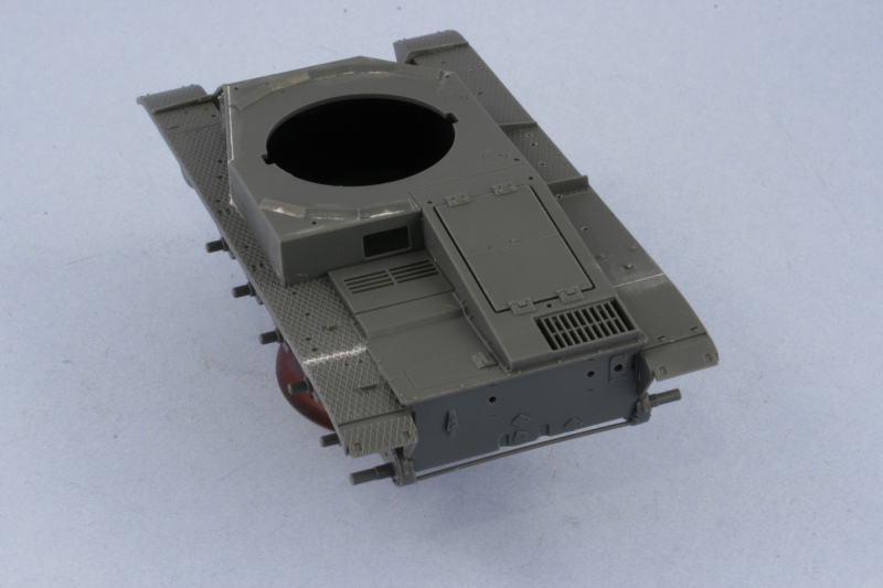
With that out of the way, I proceeded to work on Step 7 and join the upper and lower hulls. The fit here is good but the contact surfaces are not very large, so I used some rubber bands as added insurance to get a solid join all around.

Step 7 calls for the installation of the rear engine access hatch as well as the radio operator's hatch. Curiously the engine hatch actually has latch detail on the underside but since it's molded as one piece, you'd have to cut through that if you wanted to show the hatches open. The detail on the hatch is very good and the gap around the perimeter is supposed to be there just like on the real vehicle. After checking references and realizing that the fenders weren't jointed, I carefully filled the slight gap where the fender extensions met the hull from the previous step and sanded down the edges smooth.

Step 7 also adds the glacis plates and large access hatch for the driver. This fit beautifully and just required a little bit of liquid glue at the front to get the weld seam join to look the part. The correct style of view ports for the C were installed for the driver, these are called out properly on the instructions but are right next to the type for the c, A, or B so a double-check is a good idea to be sure you don't accidentally grab the wrong ones. The one piece tow rope/transmission hatch was also added along with the front tow hooks. The front fenders supports were also installed to complete the step after some ejector marks on their rear surfaces were sanded down.

Step 8 takes care of some sub-assemblies in preparation for later steps. These include the 4 part jack, the spare barrel box and lid, the two front headlights with blackout covers, the two-part antenna tray, the three-part tow hitch, and the 4 part muffler. The antenna holder had some ejector marks on the inner surfaces that I sanded down out of an abundance of caution. The muffler required the most work, with it's seam sanded down and some putty added to fill small gaps on either ends where the armored pipe from the engine and the hollow exhaust pipe installed.

Step 9 deals primarily with the rear hull plate details. The muffler is installed along with the rear brake light, the tow pintle, and the rear tow eyes. The PE mesh heat shield cover for the muffler was annealed over a gas burner flame and then carefully curved to shape using a Mission Models Multi-tool. The PE, since it's steel, is stiffer to work worth vs. brass so it took several sessions to get it to shape properly. The hull has small cut-outs molded in to take the mount tabs, so getting it into position was easy with no guess work required. The rear fender supports were also installed along with the mud-flaps. The tool box and spare barrels boxes were installed on the right side fender while the jack went on the left. The radio operator's view port was also installed and, unlike the driver's ports, this one is the earlier c/A/B type and not the C type. It's the only option provided so there was no choice there and is a minor thing in the long-run. Last but not least all the tiny little lifting eyes were added to the upper hull. No spares are available so I worked slowly and one at a time to make sure I didn't have any casualties along the way.

Step 10 deals mostly with the fender gear and I was selective in terms of what I installed and what was left off for later. The left side fender received the antenna tray, the fire extinguisher, and the long pry bar but the shovel, axe, and jack block were left off for later. All of the tools on the right fender were also left off and the front headlights were installed. I added the missing wiring conduit using 0.5mm diameter solder cut to shape and carefully glued down with liquid glue as an added detail.

Step 11 deals with assembling the commander's chair and the interior detail for his hatches. Since I'm not posing the hatches open, I skipped this step entirely.
Step 12 deals with the main armament and the first order of business is to install the MG34 and KwK 30 into the interior mantlet. Since the KwK 30 is molded as all one piece, I removed the molded on barrel portion with sprue cutters and sanded it down smooth. A mount hole was drilled with a pin vise and the Lionmarc turned brass barrel installed. The open sighting view ports were also added to the mantlet along with the circular elevation parts, the elevation parts are not glued. Only one of these receives a poly cap and the result is a very snug, but still movable, fit while the other just fits loosely on the other side elevation pin.

Next was the addition of the external mantlet plate which also serves as the turret front plate. This has to be carefully installed by getting small D-shaped tabs to align with the elevation parts.

The other half of this step is the assembly of the turret itself. The top and bottom halves were joined using a combination of regular and liquid glue and allowed to set up. The splash guard for the commander's hatches and the signal port cover were also added.

The step is completed with the installation of the mantlet and guns into the turret proper. I used a careful combination of liquid glue and regular glue, making sure that the guns could remain movable throughout. Some slight finger pressure was needed in a couple spots but otherwise a very snug fit. The main open sight hatch kept popping loose on me so I decided to pose it in the open position since that gave a larger glue surface. It also has the added benefit of the feel that the vehicle is "crewed" since most of the other hatches aside from the commander's hatch don't have any interior detail and have to be posed closed as a result.

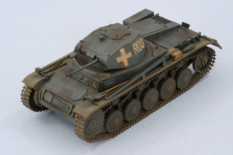
Step 14 deals with the installation of the commander's hatches and the remaining side vision ports. The turret lifting eyes were also added. I also added some weld texture to the missing areas on the angled lower turret plates by carefully scoring the plastic with the tip of a sharp #11 blade. I then came back and sanded it down to make it smaller and more regular...the photo makes the area look a little more pronounced than it actually is.

Step 15 calls for the installation of the turret into the hull as well as the addition of the rear rhomboid number plate. This was added using a drop of CA gel and some liquid glue. I also added an Armorscale 2m brass antenna (trimmed down to fit the 1.4m antenna tray) by removing the stub in the mast and drilling out a small hole and gluing it in place with CA gel. The mast was then installed to the hull side in the down position.

Incredibly as it sounds...this one's now ready for painting!


