Day 3 was even more productive than yesterday so let's get right to it!
Step 13 starts work on the superstructure for the hull. The front plate received the hull MG34 and while the instructions call for the full assembly of 7 parts, none of the interior details are visible on the finished kit so all you really need to use are parts J20 and J28. The kit also provides an option on the exterior kugelblende ball mount but the correct choice is G31 since it has the ring for the dust cover molded while the other, B3, is smooth/plain. The front plate received the driver's hood in the open position as well as the clear armored glass insert.
The step also deals with the superstructure side panels and provides the option of posing the side ports either open or closed. I opted for closed on both and also added the antenna base but not the antenna itself, will do that much later since I will be replacing the kit antenna with an AM brass one from RB Models.

Step 14 is a very busy and important step since it essentially constructs the entire upper hull from the various components all in one step. I started first with the assembly of the superstructure itself, this consists of a base that is then covered/plated over on all sides except the rear with additional parts for the roof, front, and sides. I used a combination of regular glue due to the large mating surfaces and liquid glue around the edges. Judicious use of finger pressure insured that the excellent weld detail was maintained but the join seams virtually disappeared. I set this off to the side so it could set up nice and solid for a while.

The next part of the step involves the addition of the glacis plate, this was done again with the combo of regular and liquid glue plus finger pressure. I also added part C3, the base of the Vorpanzer armor, now instead of waiting until Step 15 as it's much easier to get it in place at this stage vs. waiting until the entire upper hull was assembled. The fenders came next and these are trickier to get in place than they appear at first glance. The alignment with the fender support brackets has to be just so and there's some tension front to back that has to be ironed out as well. I started gluing at the rear and worked my way forward with each fender until I had them both secured the way I wanted them.

Next came the installation of the superstructure itself and the rear engine deck. The superstructure went in first and finger pressure was again used to get a good join before the engine deck was added.

The step also calls for the installation of the spare track holders. I added the hull nose rack first and then the glacis rack. The glacis rack's position needs to be just so to allow proper clearance between the two spare track runs especially since the spare tracks in this case are the Winterketten, so I used some of the Magic links to test fit the position relative to the front rack. I also used some poster blue-tack putty to mask off the driver's vision block to protect it during the painting and weathering stages to come. That rounded out this very important and involved step which also calls for the track installation but that will come later after painting.

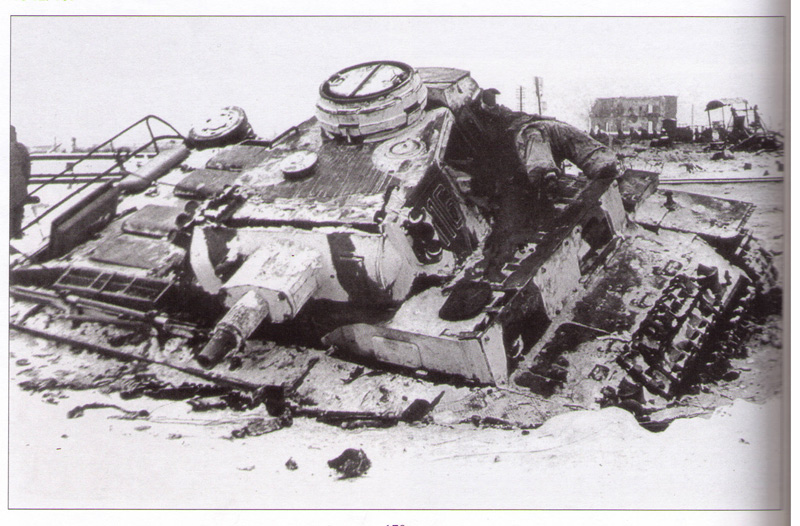
Step 15 is a small step by comparison, it adds the Vorpanzer armor to the hull front. The option is provided to use either styrene or PE parts for the small side portions and the styrene has better detail IMHO, so I used those. The side where the MG34 is located wasn't mounted starting in Sept '42 to allow the dust cover to be fitted, so I left it off on that side for accuracy sake. The top portion of the Vorpanzer is available only as a PE part, so this was removed from the fret and installed with Gator Grip glue to allow for proper positioning. The instruction diagram incorrectly shows the plate aligning all the way to the right over the MG34 mount when in fact it aligns on the opposite side since the notch in the middle has to line up with the lifting eye in the center of the superstructure roof. I also added the missing power conduit for the Notek light using 0.5mm diameter solder bent to shape and secured in place with liquid glue.

Step 16 assembles the commander's cupola. I opted for it to be closed up since I don't have any interest in displaying it open or adding a figure but the kit does provide for clear block inserts and open shutters if you wanted to go that route. It also has very nice molded details on the inside faces of the cupola hatches.

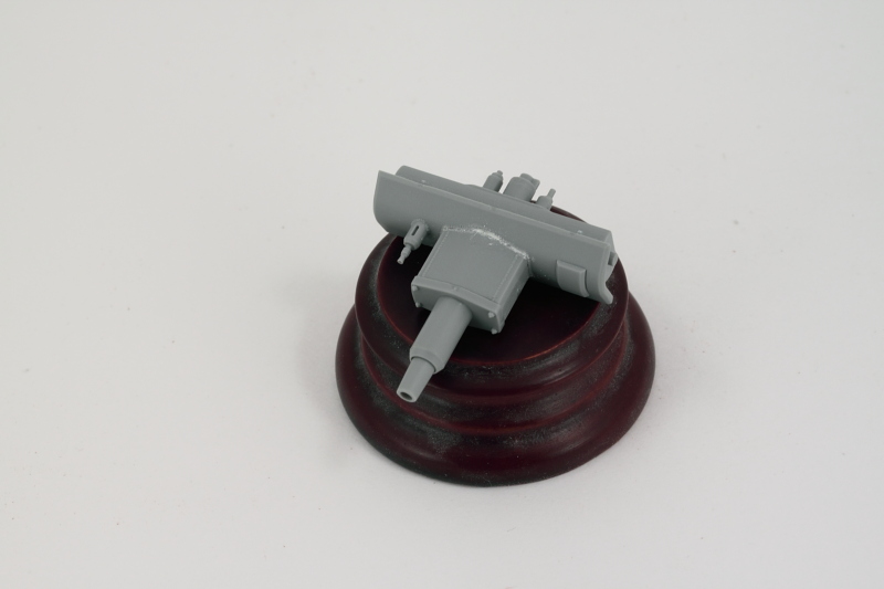
Step 17 begins work on the main gun and assembles the exterior mantlet and recoil housing as a sub-step. I chose the smooth end cap option vs. the bolted type and then added the barrel and interior mantlet portions without problems. The fit of the base of the recoil housing to the exterior mantlet isn't 100% precise so a little bit of putty was needed to fill a small gap on both the top and bottom. This step also calls for the installation of parts E2/E3 which are the elevation trunnions however it's best to wait until the next step to do that especially if you want the gun to remain able to elevate.

Step 18 adds the interior details to the gun including the breech, recoil guards, and spent shell basket. This step also adds the turret face plate to the mantlet and it's here that you should add parts E2/E3, taking care not to get glue on the mount pins. The instructions don't indicate this at all, but if you assemble it this way the gun will remain fully able to elevate but still have enough tension on the pins to hold its position however you pose it.

Step 19 begins work on the turret. The step adds the rear pistol ports and the supports for the rear turret bin. It also adds the frames for the side hatches in the form of parts G18 however the step shows these already installed and is something very easy to overlook if you aren't careful...I missed these the first time around and didn't notice them until Step 21 and it was MUCH harder to install them then of course...still possible but better if you do it in Step 19.
This step also asks you to install the turret fume extractor fan but to do that properly, you need to also install the base of the fan G6 but that isn't called for until Step 21.

Step 20 continues the work for the turret with the assembly of the turret bin and the clean-up of the turret bottom. The commander's chair is also added in this step but since I don't need it and it will only interfere with handling the turret for painting, I left it off. The turret bottom has numerous large ejector post stubs that have to be cut down and then sanded to allow for correct assembly with the turret top in the next step and of course since they are half stubs, the other half is a pin mark depression that would have to be filled and sanded if you were going to display the turret side hatches open.

That of course led me to the promised land of Step 21 which assembled the turret in its entirety from the various components constructed previously. The first order of business is to make sure you add parts G18 if you missed them in the previous step as you will need them before you can add the turret side hatches. Next you need to install the turret front plate to have proper clearance for the gun and spent shell basket to fit inside. This is a little tricky as the mating surfaces for the front plate aren't large, so I used regular glue and held it with finger pressure long enough for the glue to grab and then added the turret bottom to help support it. I used liquid glue around all the join seams and more finger pressure where needed to get a solid join all around the various weld seams.
After that had set up, I added the commander's cupola and rear turret bin followed by the various turret details as called for in the step. The side hatches were added but it's worth noting that the sub-diagram isn't quite accurate...you have to be careful which sides you use parts G19/G24 on in order to get them installed correctly. The key is the small pin molded into the hinge, this is supposed to be at the top so use that as your guide.
Last but not least, the step also provides the option for the turret-mounted smoke grenade launchers or the ordinary lifting eyes. In keeping with my Sept '42 features, I opted for the launchers. The base of the launchers has a d-shaped mounting tab but it's not the right size for the slot on the turret...so that was removed with a #11 blade and glued directly to the turret side. On the real deal the lifting eye was added over the base plate and the instructions include a sub-diagram with this option but neglect to tell you the right parts to use to do this. You need to use parts D26 (base) and D24 (hook) to add this little detail. The catch is that the round pins on the D26 base are slightly narrower than the molded-in openings on the launcher base, so you have to very carefully remove one of the round pins on D26 for it to fit right. Lot of work for a small detail, but the devil's always in the details, right?

Final step is Step 22 that places the turret on the hull in a friction fit. The fit is very loose so keep that in mind when you handle it if you place it and then forget that it's not secured!

Tomorrow will start the exterior paintwork.

