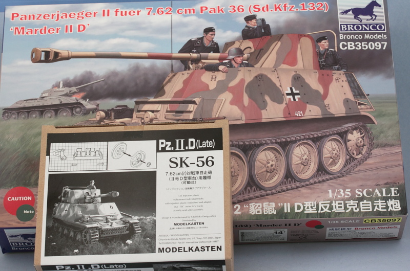
More progress to report today so let's get right down to it!
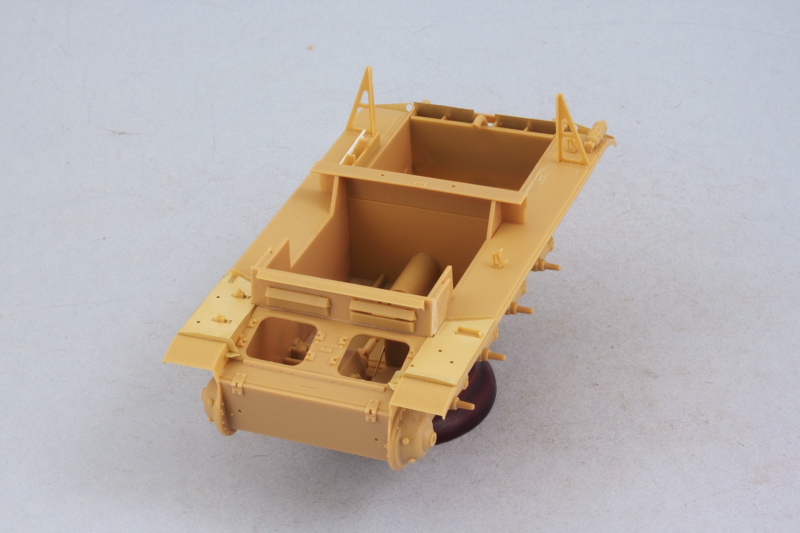
Work continued on the fenders with the addition of many of the details called for in Steps 9-11. The right side received the engine air intake and I replaced the flimsy kit supplied PE bars with rod styrene. Turns out later on in the build that this area is completely hidden away so it's not that critical either way. What is critical is the placement of the intakes and after placing the first one and doing some test fits with the rear engine deck, I realized it's actually much easier to install the intakes into the engine deck vs. trying to place them precisely on the fenders...so that's why only one is installed in the pic below.

You do need to be sure you choose the correct engine deck as there are two in the kit. I mistakenly did my test fits with the standard deck used on the II-D instead of the slightly modified one for the Marder II. Fortunately they are the same dimensions with the same placement so not a huge deal. Here you can see how the intakes fit into the deck vs. trying to place them on the fenders. I also had to modify the kit-supplied fire extinguisher by removing the rear mount pin and sanding down that area as the kit would have you leave the pin just hanging in mid-air over the fender and looking very out of place in the process.

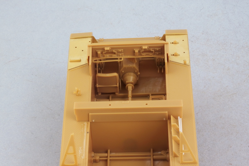
Step 12 deals with the front hull driver's plate and provides the option of installing the visors either open or closed. I closed the right side since there isn't a crew member in that position regardless but posed the driver's side visor open. The rear portion of the gun mount also installed over the firewall to round things out in this step.
There's a lot of very nice detail provided on the interior side of the plate, but no armored glass blocks.
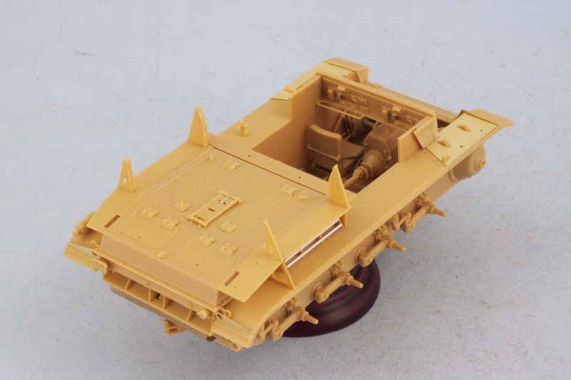
Skipping ahead a bit, I went to Step 15 to work on the rear engine deck (using the correct part this time!) and installed that in position on the hull. Once that had set up, I added all the access hatches, hinges, and lifting hooks. Bronco likes to do a lot of little parts with some of the assemblies and the rear travel lock for the main gun has this tiny little hinge trap part with tiny little pins on the lock itself. I suppose if you were really careful it could remain movable but I chose to lock it down in the stowed position.
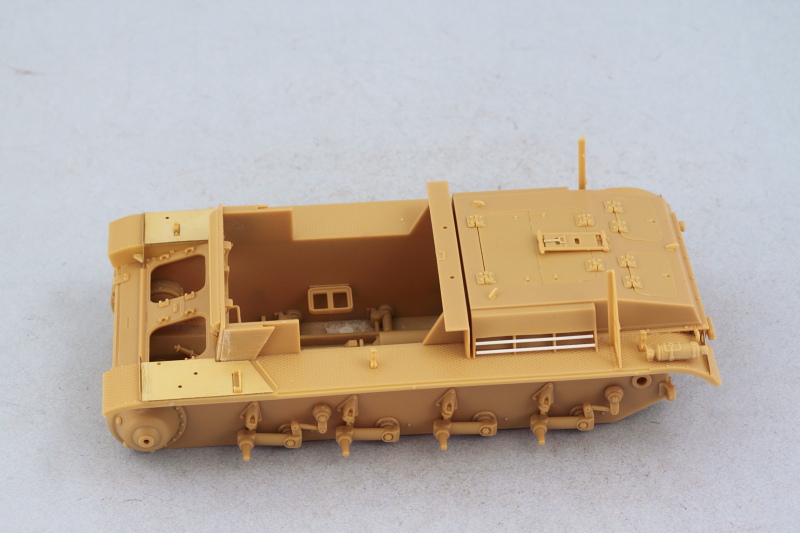
Again skipping a bit, I proceeded to Step 17 to install the rear fighting platform extensions. It's these extensions that render the previous intake work virtually unseen and the tolerances here are tight. They are designed to fit tightly over the triangular brace supports added earlier and fit flush against the hull, so if your placement of either the fenders or the braces is just a touch off, you'll have to use some elbow grease to get everything back into proper alignment. I found the little PE bracing struts for the extension to be too tall to sit properly so didn't use them as this area is practically hidden from view regardless once the fighting compartment side armor is fitted and the mesh screens in place.
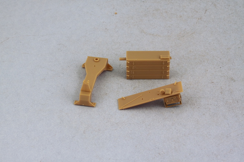
After giving it some careful thought in terms of how best to tackle the interior painting and detailing work, I decided to leave the driver's roof plate off and keep the large 8-round ammo box and gun mount base parts separate. The roof plate received its details as called for in Steps 13-14 and the gun mount base was assembled per Step 18. The vehicle's radio receiver unit was installed into the PE frame and then in position under the roof with a small hole drilled with a #76 finger drill to take the antenna wiring later on when it's installed.
The large ammo box is taken care of in Step 16. Here again is Bronco's small part tendency on display, the box is made up of two large parts but 8 tiny PE handles and another 8 tiny plastic wing nuts to get it assembled. The PE is extremely fragile and the handles are all connected together on the PE fret, making it a delicate job to remove them cleanly without bending or distorting their shapes in the process.
Next up will begin work on the fighting compartment side panels.
